


Efficient heat rejection is a fundamental requirement of industrial process design, directly impacting equipment safety, service life, and overall energy performance. Fin fan coolers—commonly referred to as air-cooled heat exchangers (ACHEs)—are the preferred solution in oil and gas, petrochemical, power generation, and heavy manufacturing facilities, valued for their consistent thermal performance and reliable heat transfer.
Unlike water-cooled systems that depend on a continuous supply of treated water, fin fan coolers use only ambient air to remove heat from process fluids. This makes them an ideal solution for facilities located in water-scarce regions, environmentally sensitive areas, or sites where water treatment infrastructure is costly to build and maintain. This comprehensive guide explains what a fin-fan cooler is, how it works, why it matters, and how to select and maintain the right unit for your application.
What Is a Fin Fan Cooler?
A fin fan cooler is a type of heat exchanger that rejects process heat directly to the atmosphere using ambient air as the cooling medium instead of water. The design consists of a tube bundle—rows of metal tubes through which the hot process fluid flows— and a fan assembly that forces or draws large volumes of air across the external surface of those tubes. Thin metal fins are attached to the outer surface of each tube to dramatically increase the available heat-transfer area without increasing the overall physical size of the unit.
The term "fin fan" directly refers to the two most visible physical elements of the equipment: the fins extending from each tube and the fan moving the cooling air. In formal engineering literature, these units are also called air-cooled heat exchangers, aerial coolers, or simply ACHEs. Regardless of the label, the operating principle remains the same — ambient air cools a hot process fluid circulating inside finned tubes. They are found on refineries, chemical plants, gas processing facilities, and power stations all over the world.
How Does a Fin Fan Cooler Work?
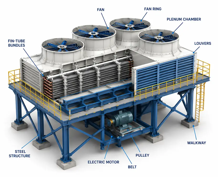
A fin fan cooler operates through the interaction between three key components: the tube bundle, the fins, and the fan-and-plenum assembly. Each plays a distinct and critical role in the overall heat rejection process.
Tube Bundle
Hot process fluid — which may be crude oil, natural gas, water, steam, refrigerant, or a wide variety of industrial liquids and gases — enters the tube bundle through an inlet header. It then travels through multiple tube passes before exiting through an outlet header at a significantly lower temperature. The tubes are typically manufactured from carbon steel, stainless steel, or special alloys selected to match the chemical properties, pressure, and temperature requirements of the specific process fluid being cooled.
Fins
Plain bare tubes offer limited surface area for air-side heat transfer. By wrapping, extruding, or brazing fins onto the outer surface, engineers can increase the effective heat-transfer area by a factor of five to twenty times compared to a bare tube. Fins are most commonly made from aluminium, which provides an excellent balance of thermal conductivity, light weight, and corrosion resistance. For more aggressive environments, galvanised steel or alloy fins may be specified. Common fin geometries include plain, serrated, and studded designs — each with different characteristics in terms of pressure drop, heat transfer performance, and resistance to fouling.
Fan and Plenum Assembly
One or more large-diameter axial fans are mounted in a structural bay either above or below the tube bundle. The plenum chamber surrounding the fan and bundle directs airflow uniformly across the full width and length of the tube bundle, ensuring that every part of the fin surface contributes to heat rejection. Without a properly designed plenum, air short-circuits around the bundle edges, and cooling efficiency drops significantly.
Forced Draft vs. Induced Draft
The airflow configuration of a fin-fan cooler — whether forced draft or induced draft — is one of the earliest and most consequential choices an engineer makes, as it directly affects cooling efficiency, equipment longevity, and site maintenance practicality. The table below summarises the key differences:
| Feature | Forced Draft | Induced Draft |
|---|---|---|
| Fan Position | Below the tube bundle | Above the tube bundle |
| Air Flow Direction | Pushed upward through bundle | Pulled upward through bundle |
| Air Distribution | Less uniform across bundle | More uniform across bundle |
| Motor/Bearing Temperature | Cooler — operates in ambient air | Hotter — exposed to discharge air |
| Hot Air Recirculation Risk | Higher in windy conditions | Lower — discharge exits at height |
| Maintenance Access | Easier — fans at ground level | Harder — fans elevated above bundle |
| Freeze Protection | Better — bundle sheltered from cold wind | Lower natural protection |
| Typical Use Case | General refinery and gas plant service | Applications needing uniform cooling |
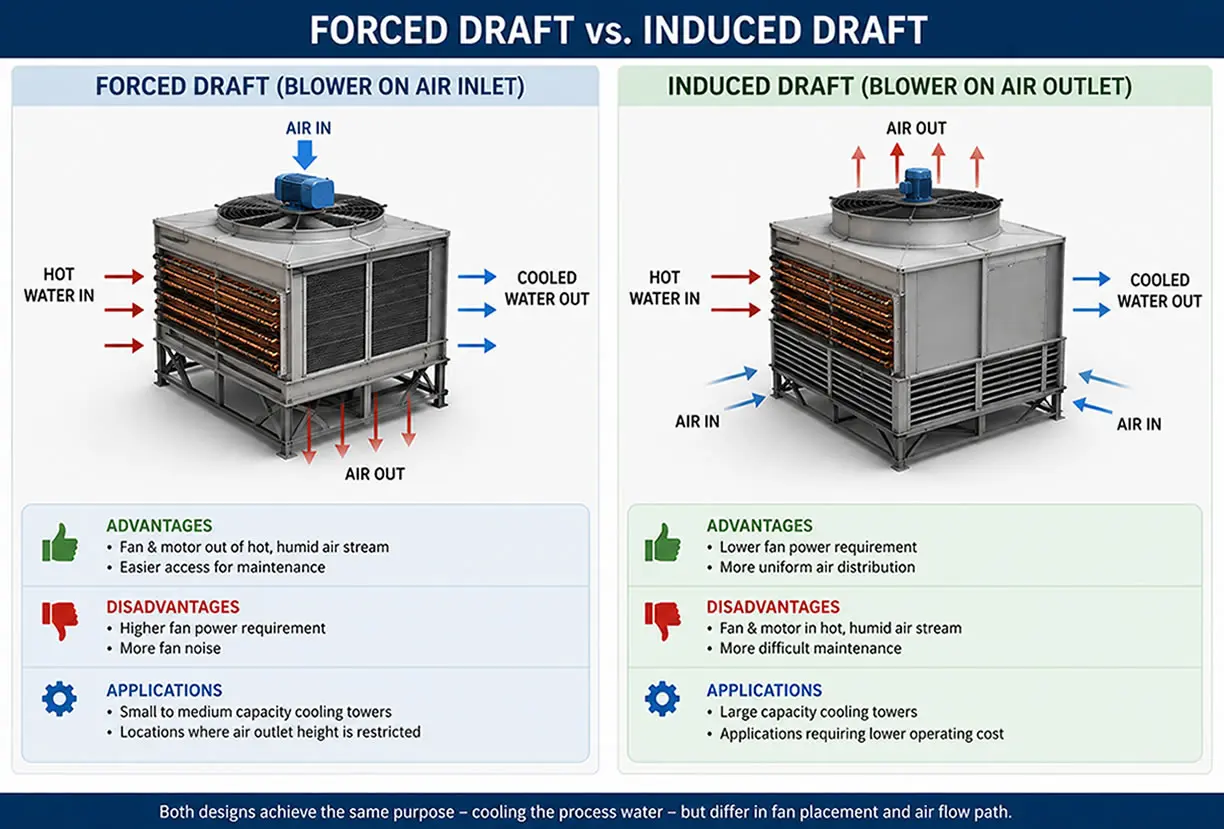
Forced-draft systems push ambient air upward through the tube bundle from below. Because the fans and motors operate in cool inlet air, mechanical components experience lower thermal stress and typically enjoy a longer service life. Crosswinds can blow hot discharge air back toward the inlet, reducing effective cooling on exposed sites.
Induced-draft systems pull hot air away from the top of the bundle. The upward exit velocity of the discharge air is higher, which reduces the risk of recirculation. Air distribution across the bundle is also more even, which improves thermal performance. The trade-off is that motors and gearboxes sit in the hot discharge air stream, increasing thermal loading on mechanical components. Hybrid configurations using variable-pitch fans or two-speed motors are increasingly popular, as they allow real-time adjustment of airflow to match changing ambient temperatures and process demands.
Key Components of a Fin Fan Cooler
Every fin fan cooler, regardless of manufacturer or application, is built around the same set of core components. Understanding each part helps maintenance teams identify problems quickly and procurement teams specify the right replacements.
Headers and Nozzles:
The inlet and outlet manifolds distribute process fluid evenly across all tube rows. Plug-type headers allow individual tubes to be accessed, cleaned, or plugged without removing the entire bundle from service.
Finned Tube Bundle:
The primary heat-transfer surface, consisting of multiple rows of finned tubes arranged within a rectangular structural frame. Bundle depth—the number of tube rows— and bay length are both determined by the required heat duty and available plot area.
Structural Frame:
A heavy-duty steel structure that supports the tube bundle, fan ring, plenum, and fan-drive assembly. The frame must be engineered to handle thermal expansion, wind loads, seismic forces, and the dynamic loads produced by rotating fan equipment.
Fan Blades:
Manufactured from aluminium, glass-fibre-reinforced plastic (FRP), or carbon fibre composite. FRP and composite blades are preferred in coastal, offshore, or chemically aggressive environments due to their resistance to corrosion and their lower weight, which reduces bearing loads.
Drive System:
An electric motor transmits power to the fan through a direct drive, V-belt arrangement, or reduction gearbox, depending on the fan diameter and rotational speed required. Variable-frequency drives (VFDs) are now widely fitted to allow fan speed to be adjusted in response to ambient temperature and process load, delivering significant energy savings over fixed-speed operation.
Louvres and Shutters:
Adjustable louvre blades mounted at the air inlet or outlet allow operators to reduce or stop airflow when needed — for example, to prevent freezing of the process fluid in cold weather, to protect the tube bundle from hail or debris, or to trim cooling capacity during low-demand periods.
Major Industries and Applications
Fin fan coolers are found wherever large quantities of heat must be reliably rejected without the use of water.
Oil and Gas Refineries:
From crude distillation overhead vapour and atmospheric residue to lube oil and intermediate hydrocarbon streams, fin-fan coolers are a standard and indispensable part of refinery heat management, ensuring every product stream reaches its required temperature before storage, blending, or further treatment.
Petrochemical Plants:
Applied to cool reactor effluents, condense product streams, and remove heat from recycle gas compressors and interstage coolers.
Natural Gas Processing:
Used to reduce gas temperature before compression, condense natural gas liquids (NGLs) after separation, and cool dehydration unit outlets.
Power Generation:
Air-cooled condensers using fin-fan technology are increasingly installed at thermal power plants in arid or water-stressed regions, replacing conventional wet cooling towers entirely.
HVAC and Data Centres:
Dry coolers and fluid coolers in large commercial buildings, district cooling systems, and hyperscale data centres rely on fin-fan technology for heat rejection without water consumption.
Renewable Energy:
Concentrated solar power (CSP) and geothermal power plants use fin fan coolers to condense the working fluid in the generation cycle, enabling operation in remote desert locations where water supply is severely limited.
Why Fin Fan Coolers Are the Preferred Industrial Cooling Solution
Zero Water Consumption:
Fin fan coolers operate entirely on ambient air. There is no make-up water demand, no blowdown, and no risk of thermal water discharge to rivers or groundwater. This is the decisive advantage in water-scarce regions and heavily regulated environments.
Reduced Fouling and Corrosion:
Removing water from the cooling loop eliminates the mineral scale, biological fouling, and chloride-induced corrosion that are the leading causes of tube failure in water-cooled heat exchangers. Process-side tube life is significantly extended.
Lower Long-Term Operating Cost:
Although the initial capital cost of air-cooled equipment is typically higher than that of an equivalent water-cooled exchanger, the elimination of water treatment chemicals, circulation pumps, blowdown disposal, and cooling tower maintenance usually results in a lower total life-cycle cost over a 25-to-30-year service period.
Less complicated site infrastructure:
There is no need for cooling-water mains, chemical injection skids, drift eliminators, or blowdown treatment ponds. This reduces civil and piping costs substantially on greenfield projects.
Environmental Compliance:
No thermal discharge plumes, no chemical wastewater streams, and no visible water vapour plume mean a smaller environmental footprint and a simpler permitting process in most jurisdictions.
Limitations and Challenges
Ambient Temperature Dependence:
The lowest achievable process outlet temperature is always limited by the local dry-bulb temperature of the ambient air. During extreme heat events, cooling performance can fall short of design conditions unless the unit has been appropriately oversized or fitted with supplemental pre-cooling.
Large Plot Area:
Air has a much lower heat capacity than water, which means more surface area — and therefore more physical space — is required to achieve the same cooling duty as a compact water-cooled exchanger.
Fan Noise:
High-volume axial fans generate significant noise levels, which may require acoustic mitigation measures on sites near residential areas or where strict occupational noise limits apply.
Higher Initial Capital Cost:
The large surface area required for air-side heat transfer means more tubes, more fins, more structure, and more fan equipment — all of which increase the upfront purchase and installation cost.
Fin Fan Cooler Selection: What to Consider
Specifying a fin-fan cooler correctly requires careful definition of the following parameters before approaching any manufacturer or engineering contractor:
Process Fluid Properties:
Flow rate, inlet and outlet temperatures, operating pressure, viscosity, density, phase condition, and any hazardous, corrosive, or fouling-prone characteristics of the fluid.
Design Ambient Temperature:
The maximum dry-bulb temperature at the site, typically taken from meteorological records at the 1% or 2% annual exceedance level to ensure the cooler performs even during the hottest days of the year.
Heat Duty:
The total rate of heat removal required, expressed in megawatts (MW) or million British thermal units per hour (MMBTU/hr), is calculated from the process flow rate and the required temperature reduction.
Plot Space Constraints:
The available bay width, length, and maximum structure height, which will determine the number of bays, tube bundle dimensions, and fan diameters that can be physically accommodated on the site.
Material Selection:
All wetted materials — tubes, tube sheets, headers, and nozzles — must be compatible with the process fluid. All external materials must be suitable for the site environment, including any risk of atmospheric corrosion, marine salt spray, or industrial chemical exposure.
Code Compliance:
Industrial fin fan coolers for refinery and gas plant service are almost universally designed and manufactured to API Standard 661. Additional compliance with ASME Section VIII (pressure vessels), local pressure equipment directives, or seismic design codes may also be required depending on the jurisdiction.
Maintenance Best Practices
Fin Cleaning:
Accumulated dust, pollen, cottonseed fibre, and industrial particulate progressively block the inter-fin passages, raising airside pressure drop and cutting heat-transfer efficiency. A regular cleaning schedule using high-pressure water washing or compressed air should be established based on local air quality and seasonal conditions.
Fan Blade Inspection:
Blades should be inspected periodically for erosion, leading-edge damage, surface cracks, and delamination in composite blades. On variable-pitch hub assemblies, the pitch-setting mechanism should be checked and lubricated at each scheduled maintenance outage.
Drive System Lubrication:
Gearbox oil should be sampled and analysed for metal contamination and viscosity degradation at least annually. V-belt tension and alignment must be verified regularly — a loose or misaligned belt is one of the most common root causes of premature bearing failure in fin-fan cooler drives.
Tube Bundle Inspection:
The external surface of the tube bundle should be inspected for fin corrosion, tube wall erosion at the inlet and outlet ends, and any signs of header plug weeping or leakage. In-place hydraulic pressure testing can confirm tube bundle integrity without requiring bundle removal, minimising downtime.
Vibration Monitoring:
Continuous or periodic vibration monitoring of fan hub bearings and motor frames enables early detection of mechanical imbalance, misalignment, and developing bearing defects. Trend-based monitoring allows maintenance to be planned in advance, avoiding unplanned shutdowns.
Frequently Asked Questions (FAQ)
Q1: What is the difference between a fin-fan cooler and a cooling tower?
A cooling tower uses water evaporation to reject heat, consuming large quantities of make-up water. A fin fan cooler uses only ambient air — no water at all. Fin fan coolers are preferred wherever water is scarce, expensive, or tightly regulated.
Q2: What materials are used for fin-fan cooler tubes?
Carbon steel is most common for standard hydrocarbon service. Stainless steel (316L, 304) suits corrosive duties. Duplex stainless handles chloride-rich environments. Titanium is used for aggressive seawater or highly corrosive service. Fins are almost always aluminium.
Q3: How is fin fan cooler thermal performance calculated?
Using the equation Q = U × A × LMTD – representing heat duty, overall heat-transfer coefficient, total surface area, and log mean temperature difference. Specialist software such as HTRI Xace or Aspen Air Cooled Exchanger is used for detailed design optimisation.
Q4: What causes fouling, and how is it prevented?
External fouling from dust, pollen, and particulate is cleared by scheduled high-pressure washing. Internal process-side fouling from waxy or scaling fluids is managed through periodic chemical treatment or mechanical tube cleaning.
Q5: Can fin fan coolers work in hot or desert climates?
Yes, with appropriate oversizing, variable-pitch fans, and optional inlet fogging or wet pre-cooling systems activated only during peak temperature periods to minimise water use.
Q6: What is the typical service life of a fin fan cooler?
25 to 35 years with proper maintenance. Tube bundles are typically the first component replaced — the structural frame, fans, and drive system often remain serviceable for the full life of the installation.
Q7: What is API 661?
The industry standard governing the design, materials, fabrication, inspection, and testing of air-cooled heat exchangers for refinery and gas plant service. Major operators and EPC contractors routinely require compliance as a purchase condition.
Conclusion
A fin fan cooler is an essential industrial cooling solution that delivers reliable heat dissipation without depending on water. Its efficient finned-tube design, low long-term operating cost, and environmentally responsible performance make it the preferred choice for modern process plants operating under increasing pressure to reduce water consumption and minimise environmental impact.
Selecting the right fin-fan cooler requires a thorough assessment of process requirements, site conditions, material compatibility, and applicable engineering standards. With correct specification, proper installation, and a structured maintenance programme, a fin-fan cooler will provide decades of dependable service — protecting process equipment, meeting environmental obligations, and supporting safe and efficient plant operation.


