An air fin cooler also known as a Fin Fan Cooler or Air Cooled Heat Exchanger is a heat exchanger that cools or condenses a process fluid by transferring heat to ambient air instead of water. The fluid flows through finned tubes, while axial fans force or draw air across the fin surface to remove heat and release it into the atmosphere.
Because no water is consumed in the process, air fin coolers are the preferred cooling technology in oil and gas, petrochemical, and power generation facilities located in arid regions or areas with strict water discharge regulations.
1. Working Principle: How an Air Fin Cooler Removes Heat
Every air fin cooler operates on one core principle:
transfer heat from a hot process fluid to ambient air through a finned tube surface, using fans to force that air movement. This is the starting point for understanding both the equipment's design and its performance ceiling.
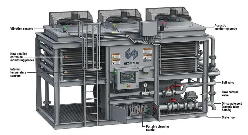
Here is a step-by-step breakdown of the process:
- Fluid entry – Hot process fluid (gas, oil, or liquid) enters the tube bundle through the inlet header.
- Convective transfer – Fans mounted below (forced draft) or above (induced draft) the bundle move ambient air across the finned tube surface, pulling heat away from the fluid through the tube wall and fins.
- Fluid exit – The cooled or condensed fluid exits through the outlet header, while the now-heated air is discharged to the atmosphere.
The critical takeaway—and the single most important constraint in air fin cooler design—is that the process fluid can never be cooled below the ambient air temperature. Unlike water-cooled systems using cooling towers, which can achieve closer approach temperatures, an air fin cooler's minimum achievable outlet temperature is always the site's design ambient temperature plus a practical approach margin, typically 8–15°C. This ceiling governs every downstream design decision, from fin geometry to fan horsepower.
2. Design Standards & Codes
Air fin coolers in refining, petrochemical, and gas processing are built to internationally recognized codes, not arbitrary specifications:
- API 661 – Primary standard for air-cooled heat exchangers; defines tube bundle design, header types, fan and driver selection, noise limits, structural design, and testing procedures.
- ASME Section VIII – Governs pressure vessel design of header boxes and tube bundles, ensuring safe operation at design pressure and temperature.
- Noise provisions (API 661) — Set maximum sound pressure levels at defined distances, critical near residential zones or under strict occupational exposure limits.
Compliance ensures both safe real-world operation and eligibility for procurement, inspection, and insurance approval on EPC and operator projects.
3. Key Components
Every air fin cooler is built from a defined set of mechanical components, each of which has design variations depending on the application.
Tube Bundle
The tube bundle is the main component for heat transfer. One of two popular techniques is used to install fins on tubes:
- Extruded fins — Aluminum is extruded over the base tube, offering excellent bonding and corrosion resistance, and is suited for higher-temperature service.
- Embedded fins – Fins are wound and mechanically embedded into a groove cut into the tube wall, providing strong thermal contact for a wide range of operating temperatures.
Headers
Headers distribute and collect the process fluid at each end of the tube bundle. Three common types are used depending on service requirements:
- Plug header – Allows individual tube cleaning and plugging without removing the entire header; most common in fouling services.
- Cover plate header – Removable plate provides full access to all tubes for inspection and cleaning; used in heavier fouling or high-maintenance services.
- Manifold header – A pipe-type header typically used in high-pressure or smaller tube-count applications.
Fans & Drives
Axial fans move air across the tube bundle and are selected based on required airflow, static pressure, and noise constraints. Drive systems include direct drive, belt drive, or gear drive configurations, paired with electric motors sized for the fan's horsepower requirement.
Louvers & Plenum
The plenum chamber directs airflow evenly across the tube bundle face, while louvers—adjustable blades mounted above or below the bundle—regulate airflow volume. Louvers are especially useful for temperature control in cold climates, preventing process fluid from over-cooling or freezing during winter operation.
4. Thermal Design
Thermal design determines an air fin cooler's real-world performance and directly impacts plant efficiency and energy use. Modern designs are modeled using HTRI (Heat Transfer Research, Inc.) methodology, simulating heat transfer and pressure drop across the tube bundle.
Key variables:
- Fin geometry — Height, thickness, and fins per inch (FPI) set effective surface area and air-side pressure drop.
- Tube rows – More rows raise heat duty capacity but also increase airside resistance and fan power needs.
- Air velocity – Optimized face velocity balances heat transfer against fan energy use and noise.
Correct thermal design avoids costly oversizing or performance-limiting undersizing at peak ambient conditions.
5. Fan System & Draft Selection
One of the most consequential design decisions for an air fin cooler is whether to use a forced-draft or induced-draft fan arrangement—a decision whose search intent around "air fin cooler types" or "forced vs. induced draft" is usually trying to be resolved.
Forced Draft
In forced draft units, fans are mounted below the tube bundle and push air upward through it.
- Advantages: Lower capital cost, easier fan and motor maintenance since components are accessible at grade or on a low platform, and lower horsepower requirements for a given airflow (since the fan handles cooler, denser ambient air).
- Disadvantages: More prone to hot air recirculation, where discharged hot air is drawn back into the fan inlet, reducing cooling effectiveness — particularly in low-wind conditions or tightly spaced installations.
Induced Draft
In induced draft units, fans are mounted above the tube bundle and pull air upward through it.
- Advantages: More uniform air velocity distribution across the tube face, significantly reduced risk of hot air recirculation, and better protection of the tube bundle from sun, rain, and debris.
- Disadvantages: Higher fan maintenance complexity since components are mounted above the hot air discharge, higher horsepower requirements (fans handle heated, less dense air), and higher structural and capital costs.
The right choice depends on plot layout, ambient wind conditions, process criticality, and maintenance philosophy. Many operators default to forced draft for standard services and reserve induced draft for critical applications where recirculation must be minimized, such as steam condensers.
6. Performance & Control
Beyond core thermal and mechanical design, several performance and control features determine how well an air fin cooler operates across varying conditions and how safely it runs over its service life.
- Noise control — API 661 and most site specifications require sound pressure levels at or below 85 dB at a specified distance from the unit, a limit driven by occupational health regulations and, in many cases, community noise ordinances. Noise is controlled through low-speed fan selection, wider fan tip clearances, and acoustic treatments.
- Winterization – In cold climates, process fluids can over-cool or even freeze if airflow isn't controlled during low-temperature periods. Winterization measures include automatic louvers, variable-pitch fan blades, fan cycling controls, and recirculation ducting to maintain minimum process outlet temperatures.
- Vibration switches – Mounted on fan bearings or drive assemblies, these switches automatically shut down a fan if excessive vibration is detected, protecting against catastrophic mechanical failure from blade imbalance, bearing wear, or structural resonance.
- Variable speed drives (VSDs) – Allow fan speed to be modulated based on real-time process temperature requirements rather than running fans at full speed continuously, reducing energy consumption and extending fan and motor life.
Together, these control systems allow an air fin cooler to operate safely and efficiently across a wide range of seasonal and operational conditions, rather than being designed only for a single worst-case scenario.
7. Applications
Air fin coolers are deployed across heavy industry wherever large-scale cooling is required without relying on a continuous water supply:
- Refineries – Cooling and condensing hydrocarbon streams across distillation, hydrotreating, and catalytic cracking units.
- Petrochemical plants – Process cooling in polymer production, ethylene cracking, and chemical synthesis operations.
- Gas processing facilities — Cooling natural gas after compression and condensing NGLs (natural gas liquids) in gathering and processing plants.
- Power stations – Steam surface condensers, lube oil coolers, and generator cooling systems in both gas and steam turbine power plants.
A major operational advantage across all these applications is that air fin coolers eliminate the need for cooling water infrastructure—no intake structures, water treatment plants, cooling towers, or discharge permitting. This significantly reduces both capital infrastructure costs and ongoing chemical treatment expenses associated with water-based cooling systems, while also removing exposure to water scarcity risk in drought-prone regions.
8. Maintenance & Troubleshooting
Reliable long-term performance depends on a structured maintenance program addressing the three most common failure points in air fin coolers.
Tube Cleaning
Fouling on the airside (dust, debris, insect buildup) or process side (scaling, deposits) reduces heat transfer efficiency and increases pressure drop. Regular fin cleaning — using compressed air, water washing, or specialized fin-cleaning tools — prevents gradual performance degradation. Process-side fouling may require chemical cleaning or mechanical tube cleaning depending on the header type installed.
Fan Balancing & Vibration Monitoring
Fan blades can become unbalanced due to dirt buildup, blade damage, or wear over time. Routine vibration monitoring, combined with periodic fan balancing, prevents excessive stress on bearings, shafts, and structural supports—and avoids unplanned shutdowns from vibration-triggered safety trips.
Header Inspection
Headers are inspected periodically for leaks, corrosion, and gasket integrity, particularly at plug and cover plate connections where seals are most likely to degrade over time. Early detection of header corrosion prevents unplanned process leaks and extends the operational life of the tube bundle.
A proactive maintenance schedule—combining routine fin cleaning, vibration monitoring, and header inspection—is the single most effective way to protect an air fin cooler's thermal performance and mechanical reliability over a 20+ year service life.
Conclusion
An air fin cooler is an engineered system, not just finned tubes and fans. It works within a fixed limit — it can never cool below ambient air temperature — and is shaped by codes like API 661 and ASME Section VIII, HTRI-based thermal design, and correct draft selection. Getting these details right delivers lower maintenance costs, no water infrastructure dependency, and stable performance across seasons. Whether specifying a new unit, replacing an old one, or troubleshooting fouling and vibration, a solid technical foundation is what separates a cooler that lasts 20+ years from a recurring maintenance problem.
Frequently Asked Questions (FAQ)
Q1: Why can't an air fin cooler cool below ambient temperature?
Heat only transfers from hotter to cooler bodies. Since ambient air is the cooling medium, the process fluid's outlet temperature is always limited by ambient conditions, typically with an 8–15°C approach margin above design ambient temperature.
Q2: What's the difference between API 661 and ASME Section VIII?
API 661 governs overall mechanical design of air-cooled exchangers, including headers, fans, and noise limits. ASME Section VIII specifically governs pressure vessel design of the header boxes and tube bundle for safe operation.
Q3: Should I choose forced draft or induced draft?
Forced draft is cheaper and easier to maintain, suited to standard services. Induced draft reduces hot air recirculation and gives more uniform airflow, making it better for critical services or tight plot layouts.
Q4: What causes reduced cooler performance over time?
Common causes include airside fouling from dust buildup, process-side scaling inside tubes, and fan imbalance from wear or blade damage. Each of these reduces heat transfer efficiency and increases pressure drop across the unit.
Q5: How is winterization handled in cold climates?
Winterization uses automatic louvers, variable-pitch fan blades, fan cycling, and sometimes warm-air recirculation ducting. These prevent the process fluid from over-cooling or freezing during low ambient temperature periods in winter operation.
Q6: What is HTRI, and why does thermal design use it?
HTRI (Heat Transfer Research, Inc.) is an industry-standard simulation platform that models heat transfer and pressure drop across finned tube bundles, helping engineers accurately size an air fin cooler for its required heat duty.
Q7: How often should an air fin cooler be inspected?
Fin cleaning and visual inspections are typically done at least annually. Vibration monitoring and header inspections often run quarterly to semi-annually, depending on service severity and site-specific reliability program requirements.
Need Help Specifying or Sourcing an API 661-Compliant Air Fin Cooler?
Talk to an engineering team experienced in thermal design, draft selection, and standards-compliant manufacturing for your exact process conditions.
Request a Technical Consultation →


