Heat Exchanger Certification
Understanding Double Pipe Heat Exchangers: A Beginner's Guide
07-11-2024

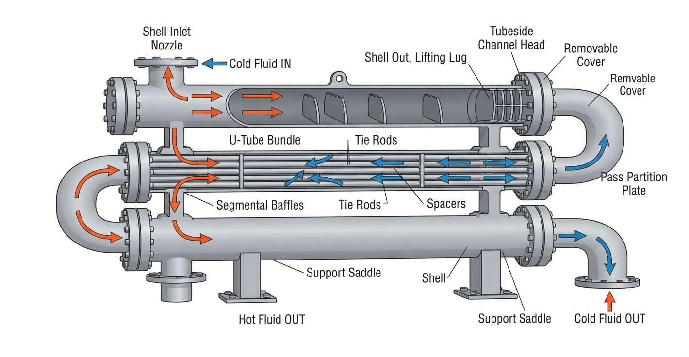
Among the many configurations used in industrial heat transfer, the double-pipe heat exchanger stands out as the most compact and mechanically simple. It's essentially a stripped-down version of the shell-and-tube heat exchanger: one pipe nested inside another, with hot fluid running through the inner pipe while a second fluid circulates through the annular gap around it. Heat passes across the inner pipe wall, and the two fluids never come into direct contact.


Because the design uses far fewer components than a full tube-bundle system, it costs less to fabricate, is easier to inspect and clean, and requires minimal downtime for maintenance. Manufacturers typically build these as U-shaped "hairpin" modules that can be linked together in series — so as a plant's cooling or heating demand grows, capacity can be added incrementally without redesigning the whole system. For engineers new to industrial heat transfer, the double-pipe exchanger is often the clearest starting point for understanding how the more complex shell-and-tube systems actually work.


Parallel Flow vs Counterflow in Double-Pipe Heat Exchangers

The direction the two fluids travel relative to each other has a major impact on thermal performance. Choosing correctly at the design stage determines how close your outlet temperature can get to the target and how much surface area you'll need to get there.

Factor Parallel Flow Counterflow
Flow direction Both fluids move in the same direction Fluids move in opposite directions
Temperature approach Larger, less efficient Closer, more efficient
Heat transfer efficiency Lower for the same surface area Higher for the same surface area
Outlet temperature limit Cold fluid can never exceed hot fluid's outlet temp Cold fluid outlet can exceed hot fluid's outlet temp
Thermal stress More gradual, gentler temperature change Sharper temperature gradient near one end
Best suited for Sensitive fluids needing controlled, gradual change Most standard process heating/cooling duties


Design Considerations for Double Pipe Heat Exchangers

Getting a double pipe exchanger right requires working through a defined sequence of engineering decisions. Here's the step-by-step process our team follows for every unit we design:

  1. Define the process duty. Establish the mass flow rate, inlet and outlet temperatures, and required heat load (duty) for both the hot and cold fluid streams before anything else is decided.
  2. Confirm fluid properties at operating conditions. Viscosity, density, specific heat, and thermal conductivity all change with temperature – use properties at the actual operating temperature, not ambient, to avoid undersizing the unit.
  3. Select the flow arrangement. Choose counterflow for maximum efficiency unless a specific process reason (like thermal shock sensitivity) calls for parallel flow instead.
  4. Calculate the required heat transfer area. Using the duty, the log mean temperature difference, and an estimated overall heat transfer coefficient, determine the total surface area needed and how many hairpin sections that translates to.
  5. Check velocity and pressure drop limits. Fluid velocity in both the inner tube and annulus must stay within a range that limits erosion and fouling on one end and excessive pumping cost on the other.
  6. Apply a fouling allowance. Add extra surface area margin based on how prone your specific fluids are to scaling, particulate build-up, or biological growth—this single factor is one of the most commonly underestimated in exchanger design.
  7. Finalise materials and mechanical rating.Verify that the design pressure and temperature rating satisfy ASME Section VIII criteria with suitable safety margins, and confirm the choice of tube and shell material against fluid corrosivity.

Double Pipe Heat Exchanger

Heat Transfer Efficiency in Double-Pipe Heat Exchangers

  1. Convective transfer from hot fluid. Heat moves from the hot fluid into the inner tube's inside wall through convection. Higher fluid velocity improves this transfer rate, up to an optimal limit.
  2. q = hᵢ × Aᵢ × (T_hot − T_wall,i) (hᵢ = inside film coefficient, Aᵢ = inner tube surface area)

  3. Conductive transfer through tube wall. Heat crosses the tube wall via conduction. Material thermal conductivity and wall thickness directly determine how much resistance this stage adds to the process.
  4. q = (k × A × ΔT) / L (k = thermal conductivity; L = wall thickness; ΔT = temperature drop across the wall).

  5. Convective transfer to cold fluid. Heat passes from the outer tube wall into the cold fluid in the annulus through convection, completing the transfer between the two separated fluid streams.
  6. q = h₀ × A₀ × (T_wall,o − T_cold) (h₀ = outside film coefficient, A₀ = outer tube surface area)

  7. Fouling resistance over time. Scale and deposits build resistance on tube surfaces, reducing efficiency gradually. Monitoring pressure drop trends catches this early, before performance visibly declines.
  8. 1/U = 1/hᵢ + Rf,i + (L/k) + Rf,o + 1/h₀ (U = overall heat transfer coefficient; Rf = fouling resistance factor).

Overall heat duty combining all four stages:

Q = U × A × ΔT_lm (ΔT_lm = log mean temperature difference between the two fluids)

This is the master equation tying the whole exchanger together—once fouling (R_f) increases in Step 4, U drops, meaning either a larger area (A) or bigger temperature difference (ΔT_lm) is needed to deliver the same duty (Q).


Industrial Applications of Double-Pipe Heat Exchangers

  • Chemical processing plants — preheating reactor feed streams and cooling product streams between process stages.
  • Oil and gas facilities — crude oil heating ahead of processing, and glycol regeneration in gas dehydration units.
  • Power generation plants — auxiliary lubrication oil cooling and sample cooling circuits for turbine and generator systems.
  • HVAC and refrigeration systems — sub-cooling and desuperheating duties in compact mechanical rooms where space is limited.
  • Food and beverage processing — pasteurisation support and product cooling where sanitary materials and easy disassembly matter.
  • Pharmaceutical manufacturing — precise temperature control in batch processing where compact, cleanable equipment is required.
  • Marine and offshore platforms — engine cooling circuits and hydraulic oil cooling where deck and engine room space are at a premium.

Advantages and Limitations of Double-Pipe Heat Exchangers

Advantages:

  1. Simple construction — fewer components mean fewer failure points and easier troubleshooting.
  2. True counterflow capability — achieves closer temperature approaches than many alternative designs.
  3. Compact footprint — fits tight plant layouts and pipe racks with ease.
  4. Modular and expandable — add hairpin sections later without a full redesign.
  5. High-pressure tolerance — cylindrical geometry handles pressure differentials well.
  6. Lower fabrication cost — economical for small-to-medium heat duties.
  7. Easy field maintenance — removable inner tube designs simplify cleaning access.
  8. Flexible material selection — adaptable to nearly any fluid chemistry or temperature range.
Limitations:
  1. Limited surface area per section — impractical for very large heat duties without many sections.
  2. Larger plant footprint at scale — a bank of hairpins takes more linear space than one large bundle.
  3. More joints and connections — each hairpin adds potential leak points versus a single bundle.
  4. Less economical per unit area at large scale — shell-and-tube designs become cheaper per square metre of surface as duty grows.
  5. Higher installation labour for multi-section banks — more piping and supports are required than for a single shell.
  6. Not ideal for very high flow rates — velocity and pressure drop limits constrain single-pass capacity.
  7. Inspection across many sections is time-consuming — each hairpin joint needs individual attention during turnarounds.
  8. Thermal expansion management — long banks of sections need careful expansion joint design to avoid stress issues.


Why Work With United Cooling Systems

We manufacture double-pipe heat exchangers, along with the full range of shell-and-tube, air-cooled, and finned-tube heat transfer equipment, from our facilities in Coimbatore, Tamil Nadu. Every unit is built to your process datasheet — not adapted from a stock design — and is hydrostatically and radiographically tested in line with ASME Section VIII and TEMA standards before it leaves our works. Our documentation package includes material test certificates, inspection reports, and as-built drawings, so your engineering team has a complete record for commissioning and future maintenance planning.


Conclusion

A double-pipe heat exchanger delivers efficient, counter-current heat transfer in a compact, mechanically simple package. Its modular design allows incremental capacity expansion, while its concentric-pipe construction handles high pressure differentials at lower fabrication and maintenance costs—ideal for small-to-medium duties across chemical, oil and gas, power, and HVAC applications. Getting the right result depends on accurate sizing and correct material selection. Share your process datasheet with our engineering team for a detailed technical proposal within 48 hours.


Frequently Asked Questions

1. What is the main advantage of a double-pipe heat exchanger?

Its simple, modular construction achieves true counterflow efficiency in a compact footprint, making it cost-effective for small-to-medium heat duties compared to larger shell-and-tube alternatives requiring a bigger fabrication investment.

2. Is counterflow always better than parallel flow?

Counterflow generally achieves higher efficiency and closer temperature approach for most applications.Only when a fluid requires more moderate and mild temperature changes to prevent thermal shock is parallel flow recommended.

3. How do I know how many hairpin sections I need?

The total required heat transfer surface area, calculated from your duty and temperature difference, is divided by the surface area available per standard hairpin section length to determine section count.

4. When should I choose shell-and-tube instead of double pipe?

Choose shell-and-tube when heat duty is large, requiring extensive surface area that would need many double-pipe sections, making a single compact bundle more space- and cost-efficient overall.

5. What causes efficiency loss in double-pipe heat exchangers over time?

Fouling — scale, sludge, or biological buildup on internal surfaces — is the primary cause. Monitoring pressure drop trends helps detect fouling early, before thermal performance visibly declines.

6. Can United Cooling Systems design a custom double-pipe heat exchanger?

Yes. We engineer every unit to your process datasheet, covering duty, materials, and section count. Share your specifications for a detailed technical proposal within 48 hours.