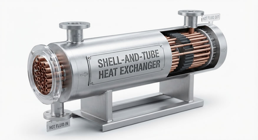
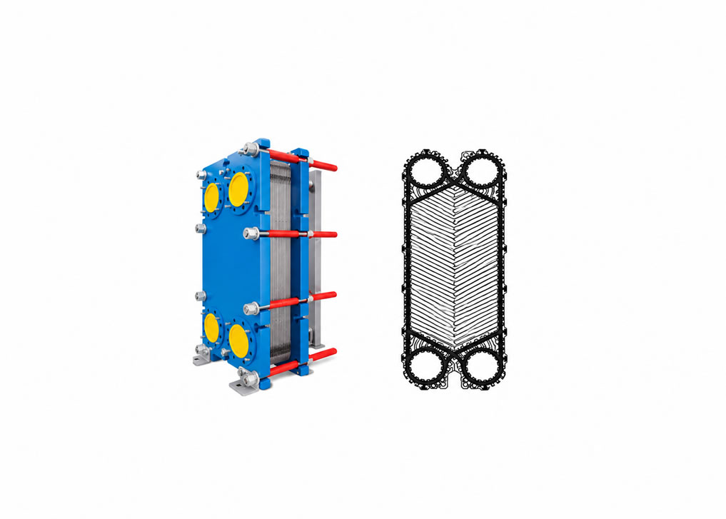
Fouling—the accumulation of unwanted deposits like biological growth, crystallization, or particulate scaling on heat transfer surfaces—drastically reduces thermal performance and increases pumping power.
Best practices for fouling control:
- Maintain high turbulence: Selecting corrugated plate patterns ensures high shear velocities that inherently discourage particle settling and scale adhesion.
- Deploy continuous monitoring: IoT-enabled differential pressure sensors and temperature transmitters detect sudden drops in thermal effectiveness early.
- Implement Clean-In-Place (CIP) regimes: Circulating specialized chemical cleaning agents dissolves mineral scaling without requiring total manual disassembly, minimizing costly facility downtime.
- Track a fouling factor trend, not just a snapshot. A single inspection tells you fouling exists; a logged trend of U-value decay over weeks or months tells you the rate, which is what actually drives a cleaning schedule.
Troubleshooting: Common Heat Exchanger Problems and Root Causes
| Symptom |
Likely Cause |
First Diagnostic Step |
| Gradual loss of duty (outlet temps drifting) |
Fouling/scaling buildup |
Check U-value trend and differential pressure history |
| Sudden pressure drop spike |
Partial blockage, debris, or gasket failure |
Inspect strainers/screens; check for gasket extrusion |
| External leakage at gasket line |
Gasket degradation, over/under-torqued plate pack, chemical incompatibility |
Verify gasket material against actual process fluid, not design fluid |
| Cross-contamination between fluid sides |
Plate crack, tube pinhole, or internal gasket failure |
Pressure/vacuum decay test or dye penetrant test on suspect plates |
| Vibration or noise in shell-and-tube units |
Flow-induced vibration, baffle spacing issue, or two-phase flow instability |
Check flow velocity against tube natural frequency; review baffle design |
| Uneven flow distribution across plates |
Poor nozzle/header design, or partial fouling in some channels |
Thermal imaging across the plate pack to spot cold zones |
Codes, Standards, and Certifications
Heat exchanger design, fabrication, and inspection are governed by a mix of pressure-vessel codes and industry-specific standards, which vary by region and application:
- ASME BPVC Section VIII (US)—pressure vessel design and fabrication rules, widely referenced even outside the US.
- TEMA (Tubular Exchanger Manufacturers Association) standards—the de facto reference for shell-and-tube mechanical design classes (R, C, B) covering severity of service.
- PED (Pressure Equipment Directive 2014/68/EU)—the EU's regulatory framework for pressure equipment, including heat exchangers, covering CE marking requirements.
- API 660 / API 662 — American Petroleum Institute standards specific to shell-and-tube and plate heat exchangers in refinery service.
- 3-A Sanitary Standards—hygienic design requirements for food and dairy processing equipment, relevant to gasketed plate exchangers in that sector.
Compliance requirements should be confirmed with a qualified mechanical or process engineer for the specific jurisdiction and application—this section is an orientation, not a substitute for code review.
Heat Recovery, Carbon Reporting, and Regulatory Alignment
Heat exchangers are one of the more direct levers a facility has for cutting reportable emissions, which is increasingly relevant as carbon disclosure frameworks tighten.
- Waste heat recovery—capturing heat from flue gas, process cooling loops, or compressor discharge and reusing it elsewhere on site—reduces fuel burned in fired heaters and boilers. That fuel reduction flows directly into Scope 1 emissions reductions, since it's combustion happening on-site and under the facility's operational control.
- Where recovered heat displaces purchased electricity (e.g., for site heating or preheating feedwater), it can also reduce Scope 2 emissions, depending on the electricity source it's displacing.
- Frameworks such as the EU's Corporate Sustainability Reporting Directive (CSRD) and similar disclosure regimes increasingly expect facilities to document energy efficiency investments, making heat exchanger retrofits and upgrades a concrete, auditable line item in sustainability reporting rather than a soft commitment.
From a board-level framing, a heat exchanger retrofit project can often be justified on energy savings alone, with the emissions reporting benefit as a secondary, reputationally valuable outcome.
Total Cost of Ownership: Capex vs. Opex Framework
A heat exchanger's purchase price is frequently a small fraction of its lifetime cost. A simple framework for comparing options on equal footing:
Practical implications:
- A cheaper, lower-U unit with a larger footprint may cost more once real estate/structural costs and pumping energy are included over a 15–20 year operating life.
- Premium alloys (titanium, Hastelloy) that look expensive on the quote often win the TCO comparison in corrosive or high-chloride service once a single avoided shutdown is priced in.
- Maintenance access cost is easy to underestimate during procurement and expensive to discover during the first turnaround—factor in crane access, bundle-pulling clearance, and spare gasket/plate inventory costs up front.
Emerging Technologies: What's Next for Heat Exchangers
- 3D-printed (additively manufactured) heat exchangers: Metal 3D printing enables lattice and triply-periodic-minimal-surface (TPMS) internal geometries impossible to machine conventionally, pushing surface-area-to-volume ratios and heat transfer coefficients beyond what corrugated plates can achieve—currently most viable in aerospace and high-value electronics cooling due to cost.
- Nanofluid coolants: Suspending nanoscale particles (metal oxides, carbon-based) in conventional coolants can measurably raise thermal conductivity, though long-term stability and erosion effects are still active research areas rather than settled industrial practice.
- AI-driven predictive maintenance: Machine learning models trained on IoT sensor streams (differential pressure, temperature, flow) increasingly forecast fouling trajectories and recommend cleaning windows before performance loss becomes a process bottleneck, rather than reacting to a fixed calendar schedule.
- Heat pump integration at industrial scale: As electrification of industrial heat gains momentum, plate heat exchangers are increasingly specified as the coupling interface between large-scale industrial heat pumps and waste-heat sources, enabling heat upgrading (raising waste heat to a usable temperature) rather than simple heat recovery.
- Direct liquid cooling for AI infrastructure: As chip power densities climb, microchannel cold plates and two-phase immersion cooling loops are pushing heat exchanger design closer to the silicon itself, with CDU-integrated plate exchangers acting as the facility-to-rack thermal interface.
Glossary of Key Terms
- Approach temperature—the smallest temperature difference between the two fluids anywhere in the exchanger; a tighter approach generally requires more surface area.
- Fouling factor—an added thermal resistance term used in design to account for expected performance degradation from deposits over time.
- NTU (Number of Transfer Units)—a dimensionless parameter used in the effectiveness method to characterize exchanger size relative to fluid capacity rates.
- Counter-current flow—fluids flowing in opposite directions through the exchanger, maximizing effective temperature difference versus parallel (co-current) flow.
- CIP (Clean-In-Place)—a cleaning method that circulates chemical solutions through the exchanger without disassembly.
- U-value—the overall heat transfer coefficient, combining conductive and convective resistances on both fluid sides plus the wall material.
Frequently Asked Questions
1. What causes a heat exchanger to lose thermal efficiency over time?
The primary driver is fouling or scaling, where mineral deposits, biological films, or process residues create an insulating layer on the heat transfer surface, raising thermal resistance and lowering the overall heat transfer coefficient (U).
2. Why are plate heat exchangers more efficient than shell-and-tube alternatives?
Plate units induce high-intensity fluid turbulence even at lower flow velocities, which breaks down fluid boundary layers and improves convective heat transfer. They also feature a true counter-current flow arrangement that maximizes the effective temperature difference.
3. How does AI optimize heat exchanger management?
Machine learning models fed by IoT sensor arrays track pressure drops, monitor fouling evolution in real time, and can flag deviations that suggest scheduling a cleaning window before performance loss disrupts the process.
4. Does a higher heat transfer coefficient always mean a better exchanger?
Not necessarily. A higher U value typically means a smaller, cheaper unit for a given duty, but it's often achieved by increasing flow turbulence, which raises pressure drop and pumping energy. The right choice depends on total lifecycle cost, not just U.
5. When does a welded plate exchanger make more sense than a gasketed one?
When operating temperature or pressure exceeds gasket limits, or when the process fluid is hazardous enough that any risk of gasket leakage is unacceptable. The trade-off is losing the ability to mechanically clean the plates.
6. What's the difference between LMTD and the NTU-effectiveness method?
LMTD is used when you already know all four terminal temperatures and want to size an exchanger. NTU effectiveness is used when you know the exchanger's physical size but need to predict outlet temperatures—common in retrofit and rating scenarios.
7. Are air-cooled heat exchangers less efficient than water-cooled ones?
Per unit area, yes—air has a much lower heat transfer coefficient than water. But where water is scarce, expensive, or tightly permitted for discharge, air-cooled (fin-fan) units avoid those constraints entirely, which can make them the better overall choice despite the larger physical size.
8. How often should a heat exchanger be cleaned?
There's no universal interval—it depends on fluid fouling tendency, flow velocity, and temperature. The better practice is condition-based: trend the U-value or differential pressure over time and clean when it crosses a defined threshold, rather than cleaning on a fixed calendar.