Heat Exchanger Certification
Shell and Tube Heat Exchanger for Oil and Gas Industry
05-11-2024

The oil and gas sector works in difficult circumstances High temperatures, high pressures, corrosive fluids, changing process conditions, and continuous operation make thermal management an essential part of production and processing. From upstream oil production to refineries and petrochemical facilities, heat must be transferred efficiently and safely between different process fluids.

One of the most widely used pieces of thermal equipment for this purpose is the shell and tube heat exchanger.

A shell and tube heat exchanger is designed to transfer heat between two fluids while keeping them physically separated. Its robust construction, ability to handle demanding operating conditions, and flexibility in material selection make it suitable for many oil and gas applications.

In this article, we explain how shell and tube heat exchangers work in the oil and gas industry, where they are used, their major components, benefits, selection factors, maintenance requirements, and common challenges.


How Do You Define a Shell and Tube Heat Exchanger?

A shell and tube heat exchanger is a mechanical device used to transfer heat from one fluid to another. It mainly consists of a large outer vessel called the shell and a bundle of smaller tubes located inside it.

One fluid flows through the tubes, while another fluid flows around the outside of the tubes inside the shell. Heat passes through the tube walls from the hotter fluid to the cooler fluid.

The two fluids normally remain separated, which is important when handling process fluids such as

  1. Crude oil
  2. Natural gas
  3. Produced water
  4. Cooling water
  5. Steam
  6. Condensate
  7. Hydrocarbon liquids
  8. Process chemicals
  9. Thermal oil

Depending on the process requirement, the heat exchanger can be used to heat, cool, condense, or partially vaporize a process stream.

Because of their strong and proven design, shell and tube heat exchangers are commonly found throughout oil production facilities, gas processing plants, refineries, petrochemical plants, and other industrial processing systems.


Why Are Shell and Tube Heat Exchangers Used in the Oil and Gas Industry?

Oil and gas processes often involve fluids at challenging temperatures and pressures. The equipment used in these facilities must be reliable and capable of operating continuously for long periods.

Shell and tube heat exchangers are widely used because they can be designed for demanding process conditions. Their construction can also be adapted according to the operating fluid, pressure, temperature, corrosion risk, and maintenance requirements.

Some important reasons for their use include:

1. Ability to Handle High Pressure

Many oil and gas processes operate under significant pressure. A properly engineered shell and tube heat exchanger can be designed to suit the pressure requirements of the shell side and tube side.

2. Suitable for High Temperatures

Refining and hydrocarbon processing can involve high-temperature streams. Shell and tube heat exchangers can use suitable materials and mechanical designs to operate under elevated temperature conditions.

3. Strong Mechanical Construction

The basic design is robust and well established. Depending on the application, the exchanger may use a fixed tube sheet, U-tube bundle, or floating head arrangement.

4. Flexible Material Selection

Materials can be selected based on corrosion resistance, fluid compatibility, operating temperature, and pressure requirements. Carbon steel, stainless steel, and other suitable alloys may be considered depending on the service conditions.

5. Suitable for Large Heat Transfer Duties

Shell and tube heat exchangers can be designed for a wide range of capacities. Multiple units can also be used where the process requires additional heat transfer capacity or operational flexibility.

6. Practical Maintenance Options

Certain designs allow the tube bundle to be inspected, cleaned, repaired, or replaced more easily than other heat exchanger configurations.


How Do Shell and Tube Heat Exchangers Operate?

The basic working principle is simple: heat naturally moves from a hotter fluid to a colder fluid.

Inside the exchanger, one fluid is assigned to the tube side, while the other flows through the shell side.

For example, hot crude oil may need to transfer heat to another process stream. The hot fluid enters one side of the exchanger, and the cooler fluid enters through another connection. As both fluids travel through their respective flow paths, heat passes through the tube walls.

The fluids do not normally mix.

A number of variables affect how much heat is transported, including:

  1. Temperature difference between the fluids
  2. Heat transfer surface area
  3. Fluid flow rate
  4. Fluid properties
  5. Tube material
  6. Fouling conditions
  7. Flow arrangement
  8. Overall heat transfer coefficient

The exchanger may operate in different flow arrangements, such as counterflow or parallel flow.

In many applications, counterflow arrangements can provide an effective temperature driving force because the two fluids move in opposite directions. However, the actual configuration depends on the thermal and mechanical design requirements.

Baffles inside the shell help guide the shell-side fluid across the tube bundle. This can improve fluid contact with the tubes and support heat transfer performance.


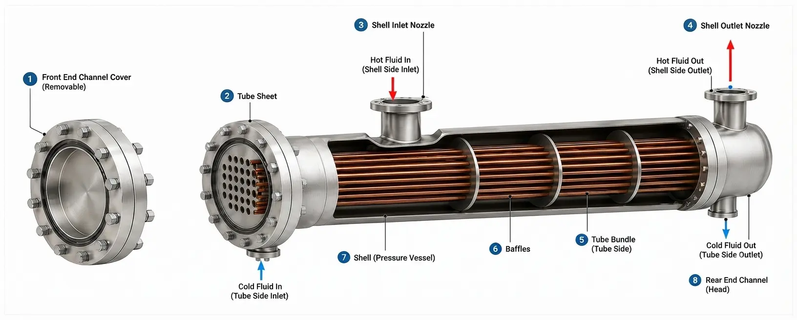
Principal Elements of a Shell and Tube Heat Exchanger

Shell and Tube Heat Exchanger

Although designs can vary, a typical shell and tube heat exchanger includes several important components.

Shell

The shell is the outer pressure-containing body of the exchanger. One of the process fluids flows through the shell around the tube bundle.

The shell design must be selected according to process pressure, temperature, fluid characteristics, and mechanical requirements.

Tube Bundle

The tube bundle contains multiple tubes that provide the main heat transfer surface.

Increasing the number or length of tubes can increase the available heat transfer area, although the final design must balance thermal performance, pressure drop, cost, maintenance, and mechanical considerations.

Tubes

One of the process fluids is carried via the tubes. Their diameter, thickness, length, layout, and material are selected based on the application.

Tube material selection is particularly important when the process involves corrosion, erosion, fouling, or aggressive chemicals.

Tube Sheets

Tube sheets support the ends of the tubes and provide separation between the shell-side and tube-side fluids.

The connection between the tubes and tube sheet must be properly designed and manufactured to reduce the risk of leakage between the two fluids.

Baffles

Baffles are installed inside the shell to direct the shell-side fluid across the tube bundle.

They can help support the tubes and influence shell-side flow behavior and heat transfer performance.

However, baffle design must be optimized carefully because excessive flow resistance can increase pressure drop.

Channel Heads and Nozzles

Channel heads provide access to the tube-side flow path. Nozzles are used for fluid inlet and outlet connections.

Their size and arrangement depend on the required flow rate and system design.


Applications of Shell and Tube Heat Exchangers in the Oil and Gas Industry

Shell and tube heat exchangers are used across the oil and gas value chain.

1. Crude Oil Heating and Cooling

Crude oil often requires temperature control before entering downstream equipment or process units.

A heat exchanger can recover heat from a hot process stream and use it to preheat a colder crude oil stream. This approach can improve overall process energy efficiency by reducing the demand for external heating.

After processing, cooling may also be required before storage or before the fluid enters another stage of the process.

2. Oil Refinery Applications

Refineries contain many process streams operating at different temperatures. Shell and tube heat exchangers can be used for heat recovery and process temperature control.

Typical duties may include:

  • Feed preheating
  • Product cooling
  • Condensation
  • Process stream heating
  • Steam and condensate services
  • Heat recovery between process streams

The exact heat exchanger design depends on the specific refinery unit and process conditions.

3. Natural Gas Processing

Natural gas processing may involve cooling, heating, condensation, and separation stages.

Shell and tube heat exchangers can be used to control the temperature of gas or liquid hydrocarbon streams. They may also be integrated with cooling systems, compression stages, and other process equipment.

Gas processing applications require careful attention to pressure, temperature, fluid composition, and the possibility of corrosion or condensation.

4. Produced Water Cooling

Produced water can contain oil, dissolved salts, solids, and other contaminants. Depending on the treatment process, temperature control may be required.

A suitable shell and tube heat exchanger can be designed to cool or heat the produced water stream while considering fouling and corrosion risks.

5. Compressor and Equipment Cooling

Compressors and other rotating equipment may generate significant heat during operation.

Shell and tube heat exchangers can be used as part of equipment cooling systems to remove heat from lubricating oil, process fluids, or other cooling circuits.

Reliable temperature control can help support stable equipment operation.

6. Condensers

In certain processes, a vapor stream must be converted into liquid.

A shell and tube heat exchanger can operate as a condenser by transferring heat from the vapor to a cooler medium such as cooling water or another suitable process fluid.

7. Reboilers and Process Heating

Some separation processes require heat input to vaporize part of a liquid stream.

Shell and tube heat exchangers can be used in reboiler services, depending on the process configuration and thermal requirements.


Types of Shell and Tube Heat Exchangers Used in Oil and Gas Applications

Different mechanical designs are available depending on thermal expansion, cleaning requirements, pressure, and maintenance needs.

Fixed Tube Sheet Heat Exchanger

In a fixed tube sheet design, the tubes are connected to tube sheets that are fixed to the shell.

This design can be relatively simple and cost-effective for suitable applications. However, differential thermal expansion between the shell and tubes must be considered during design.

U-Tube Heat Exchanger

A U-tube exchanger uses tubes bent into a U shape.

This design can accommodate thermal expansion effectively because the tubes can expand and contract. However, cleaning the curved tube sections mechanically may be more challenging.

Floating Head Heat Exchanger

A floating head design allows one end of the tube bundle to move relative to the shell.

This can help manage thermal expansion and can provide access for maintenance and cleaning. It is often used where demanding operating conditions and service requirements justify the more complex construction.

The best design depends on the actual process duty rather than simply choosing the most complex option.


Important Design Considerations

Selecting a shell and tube heat exchanger for an oil and gas application requires more than choosing a standard size.

The following factors should be evaluated.

Process Temperature

The inlet and outlet temperatures of both fluids are essential for determining the required heat duty and heat transfer area.

Operating Pressure

Shell-side and tube-side pressures may be different. The exchanger must be mechanically designed for the relevant operating and design conditions.

Fluid Properties

The density, viscosity, specific heat, corrosiveness, solids content, and other fluid properties can affect the thermal and mechanical design.

Fouling Tendency

Some oil and gas fluids can create deposits on heat transfer surfaces. Fouling can reduce heat transfer efficiency and increase pressure drop.

The exchanger design should consider cleaning methods and expected fouling behavior.

Corrosion Risk

Corrosion can affect the shell, tubes, tube sheets, and other wetted components.

Material selection should be based on the actual fluid composition and operating environment.

Pressure Drop

An excessively high pressure drop can increase pumping or compression requirements. The design should balance heat transfer performance with acceptable pressure losses.

Maintenance Requirements

The ability to inspect and clean the tube bundle may be an important factor, especially for services with significant fouling potential.


Benefits of Shell and Tube Heat Exchangers for Oil and Gas Operations

A properly selected shell and tube heat exchanger can provide several benefits.

Reliable Heat Transfer

The large heat transfer surface created by multiple tubes makes the design suitable for many industrial thermal duties.

Process Flexibility

The equipment can be designed for heating, cooling, condensation, and other heat transfer requirements.

Durable Construction

With appropriate design and material selection, shell and tube heat exchangers can provide reliable service in demanding industrial environments.

Energy Recovery Opportunities

Heat from one process stream can sometimes be recovered and used to heat another stream. This can reduce the overall demand for external heating or cooling.

Serviceability

Depending on the exchanger design, tube bundles may be inspected and cleaned during scheduled maintenance.

Custom Engineering Options

Shell diameter, tube arrangement, materials, number of passes, and mechanical configuration can be adapted to meet specific process requirements.


conclusion

Common Problems in Oil and Gas Heat Exchangers

Even a well-designed heat exchanger can experience performance problems if operating conditions change or maintenance is neglected.

Fouling

Deposits accumulate on heat transmission surfaces and cause fouling.

Possible causes include:

  • Oil and hydrocarbon deposits
  • Scale
  • Sediment
  • Corrosion products
  • Biological growth in water systems
  • Suspended solids

Fouling reduces heat transfer efficiency and may increase pressure drop.

Corrosion

Corrosive process fluids can damage heat exchanger components over time.

Proper material selection, process control, monitoring, and inspection are important for reducing corrosion-related failures.

Tube Leakage

Tube damage can allow one process fluid to leak into the other side of the exchanger.

This can create operational, environmental, or safety concerns depending on the fluids involved.

Vibration

Improper flow conditions can contribute to tube vibration.

Over time, excessive vibration may cause mechanical wear or tube damage. Proper mechanical and thermal design is important for managing this risk.


Maintenance of Shell and Tube Heat Exchangers

Regular maintenance can help maintain thermal performance and identify problems before they become more serious.

A maintenance program may include:

  • Monitoring inlet and outlet temperatures
  • Checking pressure drop
  • Inspecting for leaks
  • Inspecting accessible components
  • Cleaning tubes when required
  • Monitoring corrosion
  • Performing appropriate non-destructive testing
  • Inspecting gaskets and connections
  • Reviewing operating conditions

Cleaning methods depend on the exchanger design and type of fouling. Mechanical cleaning may be possible for straight-tube arrangements, while chemical cleaning may be considered where appropriate and compatible with the equipment materials and process requirements.

Maintenance should always follow the equipment manufacturer's recommendations and the operating facility's approved procedures.

How to Select the Right Shell and Tube Heat Exchanger

The right heat exchanger should be selected based on actual process data.

Before finalizing a design, engineers typically evaluate:

  1. Required heat duty
  2. Hot and cold fluid temperatures
  3. Flow rates
  4. Operating and design pressures
  5. Allowable pressure drop
  6. Fluid properties
  7. Corrosion potential
  8. Fouling tendency
  9. Required materials
  10. Maintenance and cleaning requirements
  11. Available installation space
  12. Applicable design and safety requirements

Providing complete and accurate process information helps ensure that the selected exchanger is suitable for the intended duty.

A heat exchanger that is oversized, undersized, or designed using incorrect process assumptions may lead to unnecessary cost or poor thermal performance.


Frequently Asked Questions

1. What is the difference between shell-side and tube-side fluids?

The tube-side fluid flows inside the tubes, while the shell-side fluid flows around the outside of the tubes within the shell. The choice of which fluid goes on which side is a design decision based on factors such as pressure, corrosiveness, fouling tendency, and ease of cleaning.

2. Can a shell and tube heat exchanger handle two-phase flow?

Yes. Shell and tube exchangers are commonly used as condensers (vapor to liquid) and reboilers (liquid to partial vapor), in addition to single-phase heating and cooling duties. The mechanical and thermal design must account for the phase change involved.

3. How is TEMA used in shell and tube heat exchanger design?

TEMA (Tubular Exchanger Manufacturers Association) standards provide widely recognized guidelines for the mechanical design, fabrication, and classification of shell and tube heat exchangers and are commonly referenced in oil and gas project specifications.

4. How frequently should a shell and tube heat exchanger be cleaned?

Cleaning frequency depends on the fouling tendency of the process fluids, operating conditions, and monitored performance indicators such as pressure drop and heat transfer efficiency. There is no universal schedule—cleaning intervals are typically determined by facility experience and condition monitoring rather than a fixed calendar interval.

5. What codes and standards commonly apply to these exchangers?

Depending on the region and project, shell and tube heat exchangers used in oil and gas facilities may need to comply with standards such as ASME (pressure vessel design), TEMA (mechanical configuration), and relevant client or regulatory specifications. Applicable requirements should always be confirmed for the specific project and jurisdiction.


Conclusion

The shell and tube heat exchanger remains an important part of the oil and gas industry because of its robust construction, design flexibility, and ability to handle a wide range of thermal duties.

It is used in crude oil processing, refineries, natural gas facilities, equipment cooling systems, condensers, reboilers, and heat recovery applications. Different configurations, including fixed tube sheet, U-tube, and floating head designs, can be selected according to operating conditions and maintenance requirements.

For reliable performance, the heat exchanger should be engineered using accurate process data and appropriate consideration of pressure, temperature, fluid properties, corrosion, fouling, pressure drop, and serviceability.

When properly designed, operated, and maintained, a shell and tube heat exchanger can support efficient heat transfer and reliable process operation across many oil and gas applications.